Commonly Ignored Feature #5: Using multiple UV maps

uvs

Unfortunately the Texture Coordinate node only gives us the active UV map (as indicated by the highlighted camera icon) and gives us no way of choosing which UV map we want.

Luckily we have the Attribute node. Simply enter the name of the UV map you want and connect the Vector output to anything you like to use those coordinates.

attributeuvs

That’s it. Yeah a short and quick CIF this weekend, I’ve got a tight deadline and am fighting bugs… more on that later.

Killing Caustics Cleverly

Alliteration aside, this blew my mind.

joined2

The two images above were both rendered in nearly 18 minutes on a 12 core i7 CPU. All materials and settings everywhere were exactly the same… sort of.

I’ve been playing with image stacking lately, mainly as a tool to render images and animations progressively, but when rendering some glass the other day, I realized that the only reason it renders so slow is because the noise and fireflies don’t change all that much, only more and more of it gets added and eventually averaged out. So if we change the noise pattern and render less samples a couple of times…

Continue Reading…

Commonly Ignored Feature #4: UVs are Colours

Not just UVs, but any texture coordinate.

tex_uvs


If you connect the UVs of an (unwrapped) plane to a shader’s colour, this is what you’ll see. Basically, texture coordinates are simply an ‘image’ of sorts, where the red value corresponds to the X-axis, and the green value corresponds to the Y-axis (and for 3d coordinates like Generated or Object, blue is the Z-axis.)

Why do we care?

It allows us to manipulate these coordinates as if they were colours (which I suppose they are):

tex_distort


Here I’ve simply added a Musgrave texture to the UVs, and plugged that into the Vector input of the image texture:

tex_shift_nodes


Don’t forget that, except in the case of shaders, a socket’s colour is only a visual indication of the data it gives/takes and not a strict law – vectors and colours are essentially the same thing, three values, hence we can mix them up and use them together.

But those bricks look ugly you say? Well yeah. A more practical example would be to use the Random output of the Object Info node (yeah, again) to give each object (which have the same UVs) different offsets – so if you have a billion objects that are all the same, an easy way to break up the repetitiveness is to change the texture coordinates of each of them randomly.

tex_shift


That’s all folks!

I’m trying to post these ‘Commonly Ignored Features‘ twice a week, so let me know if you think of something I could share!

Commonly Ignored Features #3: Object Index Node

gumballs

Now before you ignore me, I’m not talking about compositing here. I’m talking about the Object Index output of the Object Info material node:

object_info

The cool thing about this is that if you give a whole bunch of objects a single material, then you can still vary the material for each object by using the Object or Material index:

passindex2

In the image at the top, I used a little bit of python to give each selected object a random index inside a certain range:

import random
for obj in bpycontext.selected_objects:
    obj.pass_index=int(random.random()*(640-440)+440)

The range (between 440 and 640) is actually the range of colours in wavelengths. So plugging that into the wavelength node will give me a random colour for every object:

wavelength_gumballs

But we could do that with the Random output of the same node, albeit with less control, so here’s an even better example:

When you have a bunch of objects using the same material and you only want to change one of those objects, for example scale the texture up or down, you can use that object’s index as a mask and mix two things together with it. In the case below, making the object that has a pass index of 5 use tighter textures:

passindexSince we currently lack an “Equal To” mode for the math node, we need to use the product of Less Than and Greater Than modes. The object index is an integer, so using 5.1 and 4.9 for those nodes respectively we can be sure that we’re only getting the index of 5.0

Optimization Tip:

The mapping node’s Scale ability is really just multiplying the UVs (which is really just an ‘image’ where red and green represent X and Y coordinates, plug the UVs into an a shader’s colour if you don’t believe me). So instead of using two mapping nodes in the example above, use a Colour Mix node on Multiply with the same scaling values for the R, G and B and use the Object Index for it’s Fac.

Metropolis

image

I worked on this for a good couple days… it’s not finished, but I suppose it’s slightly usable.

There aren’t many city generators available for blender… in fact I only know of one, which is great but not very versatile. You kinda get what you get. What I wanted was a city generator that was so customizable that you could create any shape city of any layout of any scale on any planet… yeah. Obviously if it demands such vast possibilities, it can’t all be automated.

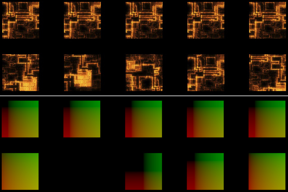
The plan was to have the user give it a set of buildings, a few images for scale/height maps and terrain stuffs, and even give it the street layout. The automation part is simply the placement of buildings along the streets. Simple. Yeah.

It’s probably the most complex stuff I’ve ever coded, not the hardest, just a lot going on to keep track of and integrate, while still keeping everything very customizable. It’s about 600 lines, which I suppose isn’t all that much to a seasoned coder, but for me it’s much more than anything I’ve done before :P

Placing buildings mostly evenly spaced and along a street is pretty easy, the challenging bit was preventing buildings from being created in the middle of an intersection, and along many curves at once without overlaps.

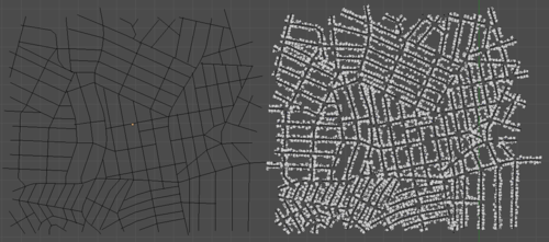
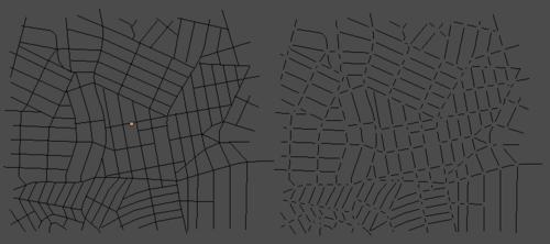
The solution was to increase the curve’s resolution a lot, convert them to meshes and join them all into one object. Then do a Remove Doubles to weld vertices that are close together. Why? Because this will join the lines together, making a vertex at each intersection that connects to both/all streets. Which means a simple search for verts with more than 2 edges connected will give us the position of the intersections!

image

Deleting these intersection verts, separating the object by loose parts and converting it back to curves will give us the perfect set of curves to but the buildings on to make sure no buildings sit in the middle of an intersection.

imageAnd that’s pretty much as far as I got. So it’s functional… just not really useful.

When I next feel like working on this, I’ve got a long list of todo’s… so probably not for a while.

The end goal would be to include a building generator and stuff like that too. I seriously considered turning this into a kickstarter, but at the moment I don’t really have the experience nor the time for something as epic as this.

Baking for Cycles

I stumbled upon a thread on BlenderArtists the other day – a guy called Simon Flores wrote a script that allows you to bake stuff in cycles and any other render engine for that matter.

bake_cycles

I wouldn’t quite call it baking, but in simple cases it could be quite useful. It goes through every face in the whole scene and places the camera facing it, renders it, and at the end of all that it joins all the pieces together. Genius right? Sort of.

It’s a great start, but there are some serious limitations:

  • The object you’re baking must be clear of any obstructions otherwise the camera cannot see it. That means that any non-manifold meshes will have artifacts
  • It’s really really slow, rendering a whole image for every single face. It took several minutes to bake a couple cubes.
  • The meshes must be triangulated first, since it can’t work with quads.
  • All meshes must be UV mapped and have the same image assigned to them in BI before baking (with no overlapping UVs of course)
  • Did I mention how slow it is? I started baking the Matball used on the wiki, with just 20 samples it was going at about 0.001% per second. That’d take 28 hours.
  • Since it places the camera on each face, any view-dependent shaders (like glossy, glass and anything with fresnel) will come out really weird.

If you can ignore or manually fix those limitations, then I’m sure you could do some pretty powerful stuff with it, perhaps creating a GI lightmap for a game. For now, I’ll wait until someone takes Simon’s code and gives it a UI and addresses some of those limitations. And speeds it up. A lot.